


INTRODUCTION
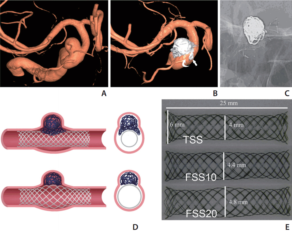
Endovascular aneurysm treatment has proven to have better outcomes than clipping for intracranial aneurysms [1-3], and with the advent of various self-expanding stents that served as scaffolds to prevent coils herniating into the parent artery (PA), wide-neck aneurysms (WNAs) have also become an indication for endovascular embolization [4-7]. However, use of stent-assisted coiling with a tubular-designed stent for WNAs is sometimes difficult because of dilation of the vessel lumen of the PA, which may cause inappropriate abutting of a stent to the vessel wall and incomplete coverage of the ostium [8]. Dilation of the PA had been reported as a not uncommon morphological abnormality in the distal internal carotid artery (ICA) with WNAs [9,10]. Although the push-and-pull technique can make the middle part of a braid stent bulge to provide better mesh coverage at the ostium and better vessel wall apposition, the result is not satisfactory sometimes because of the limitations of the original design (Fig. 1A-C).
To overcome the limitations of currently available tubular-shaped stents (TSSs) in the treatment of WNAs with a dilated PA, we hypothesized that a self-expanding fusiform-shaped stent (FSS) designed with a bulging middle segment would achieve better wall apposition and better ostial coverage as well (Fig. 1D). The purpose of this in vitro study was to prove the concept of the FSS device for the endovascular treatment of WNAs associated with a dilated PA using a three-dimensional (3D) aneurysmal model.
MATERIALS AND METHODS
Fabrication of TSS and FSS
We fabricated three different prototype self-expanding stents by weaving a 0.0025-inch-diameter Nitinol wire (Furukawa Techno Material Co. Ltd., Kanagawa, Japan) (Fig. 1E). TSS was designed to have a body diameter of 4 mm and a length of 25 mm. Both ends were flared with the maximum diameter of 6 mm at the margin. The two ends of the FSSs (each end one third length of the stent) were basically same with TSS, whereas the mid portion had a bulging shape (mid one-third segment). We made the FSSs with two different diameters of the bulging segment. FSS10 is an FSS with a bulging segment maximum diameter of 4.4 mm, 10% greater than the nominal body diameter. FFS20 has a bulging segment maximum diameter of 4.8 mm (20% greater). Each type of stent was prepared as a pair to give six stents in total.
Silicone aneurysmal model
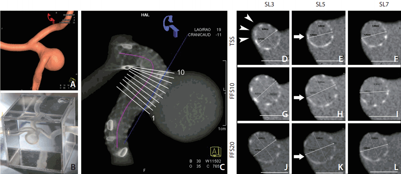
A wide-neck distal ICA aneurysm associated with localized PA dilation was chosen (aneurysm volume of 535 mm3, ostium size of 8.5├Ś7.0 mm, proximal PA diameter of 4.0 mm, and distal PA diameter of 4.8 mm). Simplified 3D volume data from rotational angiography was obtained from the volume-rendering image obtained on a Leonardo workstation (Siemens Healthcare, Erlangen, Germany) (Fig. 2A) and used to generate a rapid 3D printing prototype on a 3D printer (Project 3510 SD; 3D Systems, Rock Hill, SC, USA). Six silicone aneurysmal models were manufactured and mounted on a transparent acryl box full of silicone gel (Fig. 2B).
Stent placement and angiography
The silicone vascular model was connected by a closed circuit and infused with warm saline by using a peristaltic pump (Ecoline VC-280; Ismatec, Wertheim-Mondfeld, Germany). 11 The tip of the 6-Fr guiding catheter was placed right below the proximal stump of the silicone aneurysmal model. The stent was delivered through a 0.027-inch-sized microcatheter (Excelsior XT-27; Stryker Neurovascular, Fremont, CA, USA). A push-and-pull technique was used to place the stents under fluoroscopic guidance (Axiom Artis; Siemens Healthcare). The operator was blinded to the stent type during deployment of the stent to avoid bias caused by the delivery technique. The aneurysmal model was primed with 10% saline-diluted iodine contrast media (Visipaque 270; GE Healthcare, Princeton, NJ, USA), and then volume-rendering and maximum intensity projection (MIP) images were obtained on the Leonardo workstation. For MIP, the contrast was adjusted so that the stent mesh could be differentiated from the vessel lumen and aneurysmal sac that were filled with diluted contrast media (Fig. 2C). Each of the six stents (three pairs) was placed in each of six silicone aneurysmal models; thus, 12 sets of data for each type of stent were acquired.
Image analysis
Imaging parameters were measured by using the vessel analysis tool in the Leonardo workstation and ImageJ (NIH, Bethesda, MD, USA). We developed several parameters to investigate the efficacy of the stents. ANOVA was used to compare the repeated test results (Stata 12.0 for Mac [64-bit Intel]). Bonferroni correction was performed for post hoc analyses.
Centerline distance and stent expansion at the neck portion
By using the vessel analysis tool of the Leonardo workstation, a centerline was drawn along the stented segment of the PA to measure the shortening or lengthening effect of the stents (Fig. 2C). We placed 10 different cross sections perpendicular to the centerline at the aneurysm ostium portion to measure the stent lumen area (cut-surface area) (Fig. 2C-L).
Stent mesh coverage at the aneurysmal ostium and cell area at the convex side
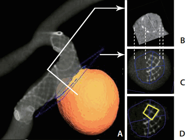
By placing a cutting plane at the neck that separated the aneurysmal sac from the PA, we could measure the stent-covered area and the non-covered area at the ostial portion (Fig. 3A-C). The cell area at the ostium portion was measured to see whether there was any stent deformity at the convex side. We chose the largest four-cell area at the profile view of the aneurysmal sac along the convex side of PA (Fig. 3D) because the larger stents gave better expansion.
Stent wall apposition in the proximal and distal PA
The proximal and distal PA segments covered by the stent mesh were chosen to obtain the cross-sectional images. Wall apposition to PA was measured by determining the ratio of the cross-sectional areas of the stent and PA lumen. The ratio was regarded as good when it was >0.8.
RESULTS
Centerline distance and stent expansion at the neck portion
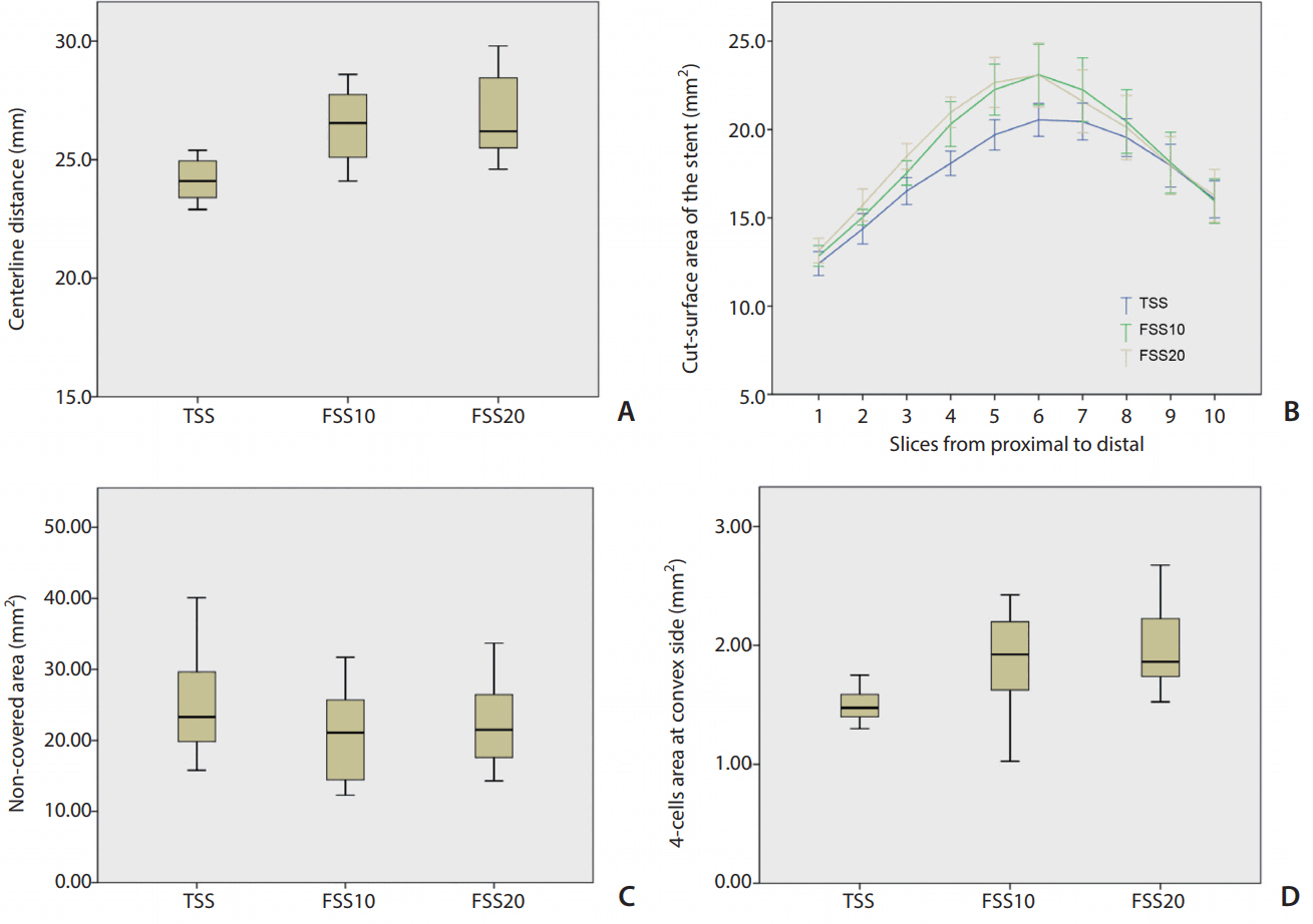
The centerline distance was significantly longer in both FSS10 and FSS20 than in TSS (P=0.006 and P=0.001, respectively). There was no significant difference between FSS10 and FSS20. In comparing the cut-surface areas of the stent lumen, significant differences were noted among the stents (P=0.046). Post hoc analyses revealed that both FSS10 and FSS20 showed significantly larger cut-surface areas than those of TSS (P=0.024 and P=0.018, respectively), but there was no significant difference between FSS10 and FSS20 (Fig. 4).
Stent mesh coverage at the aneurysmal ostium and cell area at the convex side
The non-covered area at the ostium tended to be smaller in FSS10 and FSS20 (P=0.327). The four-cell area at the convex side was significantly different among the stents (P=0.002) and was significantly larger in both FSS10 and FSS20 than in TSS (P=0.018 and P=0.003, respectively), but there was no difference between FSS10 and FSS20 (Fig. 4).
Proximal and distal vessel wall apposition of the stents to the wall
There was no significant difference in wall apposition among the stents in the proximal and distal segments of PA (both P>0.05). However, when we compared the wall apposition ratio between the proximal and distal segments, we observed significantly better wall apposition in the proximal segment for all three types of stents (P<0.05). The mean wall apposition ratios at the proximal and distal segments were (0.86┬▒0.04 and 0.79┬▒0.08, respectively; P<0.001). However, the wall apposition ratio at the distal segment was acceptable.
DISCUSSION
In the current study, we compared the efficacy of three types of self-expanding braided-type stents in the treatment of WNAs with significant PA dilation. Compared with TSS, both FSS10 and FSS20 showed better stent expansion, vessel wall apposition, and aneurysmal neck coverage as well as less stent shortening.
The novel fusiform shape in the middle part of the tested stent design demonstrated its advantages mostly in two aspects. First, the good expansion of the middle part of the stent led to good apposition to the vessel wall at the segment of the aneurysmal neck, which may decrease delayed complications, such as stent thrombosis, caused by incomplete apposition of the stent [10]. Though an oversized tubularshaped stent can achieve acceptable vessel wall apposition at the segment of the aneurysmal neck, the two ends will not get full expansion due to its larger diameter compared with the vessel lumen. Second, good expansion also resulted in better coverage of the ostium. The uncovered areas were relatively smaller in FSS10 and FSS20 than in TSS, which indicated that FSS can block protrusion of the coil back into the PA better than can TSS, and therefore, may avoid the irregular residual space between the stent and vessel wall and keep the inner surface of the lumen smooth (Fig. 1B). Apart from the simple braided stent, a fusiform stent may also be used in a flow-diverter to achieve a better wall apposition.
We noted that the currently available braided tubular design stents, such as the LVIS (MicroVention, Tustin, CA, USA), which is similar to the TSS in this study, may work to some extent similarly to our FSS [12,13]. Intentional push-pull maneuvering during delivery of the stent may create a fusiform shape in the middle segment of the stent at the dilated PA [14]. In this study, all three types of stents were deployed with the same push-and-pull technique by the same operator; however, a significant difference was still observed between TSS and FSS10/FSS20 in the vessel apposition and aneurysmal neck coverage. Due to the initial fusiform design, the homogeneity of the mesh density would be better with a FSS than a TSS after deploying the stent with the push-and-pull technique. Compared with a TSS, a FSS does not need as much power to create the fusion form part, which can decrease the mechanical stress on the vessel wall and thus decrease the risk of intima injury. Additionally, the fusiform design of the stent decreases the shortening of the centerline distance relative to that of a TSS, which may facilitate accurate deployment of the stent.
Recently, the Barrel vascular remodeling device (Medtronic, Irvine, CA, USA), which is a self-expandable laser-cut stent developed with a bulged center section, was introduced for stent-assisted coil embolization of wide-necked bifurcation aneurysms [15]. The stent was designed particularly for bifurcation aneurysms, and no experiences of use in side wall aneurysms with PA dilation have been reported yet. Considering the Barrel device for supporting the wide neck of a bifurcation aneurysm obviates use of multiple stents, we thought that this fusiform design might also be used for the same purpose.
The FSS and the TSS showed similar vessel wall apposition at both the proximal and distal portions of the stent. With both the FSS and the TSS, the proximal apposition was better than that of the distal portion, which may be attributed to the case-specific vessel geometry and push-and-pull technique. When we began to deploy the stent, there was not too much friction between the stent and vessel wall, so the wall apposition of the stent at the distal portion depended on the self-expansion of the stent. While at the end of deployment of the stent, the stent is immobilized by the vessel and the push-and-pull action can lead to better wall apposition. Future studies will be conducted to test if case-specific geometry prototypes will affect the apposition.
In the current study, we presented a fast 3D prototyping method for a case-specific vessel with radiographic volume information that has greater efficiency than that of an animal model for evaluation of device morphological designs and can be used to preliminarily study the efficacy of a stent before an in vivo study. The parameters applied to evaluate the efficacy of the stent can be correlated with clinical outcomes in the future and used to evaluate clinical prognosis. However, in vivo animal experiments are still necessary for making quantitative guides for choosing the size of the fusiform stent.
There were several limitations of this in vitro experiment that should be considered. First, only one wide-necked distal ICA aneurysm model was used. Because a variety of factors may affect wall apposition of a stent, such as vessel tortuosity and lumen discrepancy proximally and distally to the aneurysm, the stents should be tested in more models with different configurations. Second, our results were limited to braided stents, so we cannot generalize the results to laser-cut stents, since they tend to behave differently in the same PA morphology. Third, the silicone aneurysmal model cannot simulate all features of a human artery, so before human trials, animal experiments are necessary to test its biocompatibility.
CONCLUSION
Our results showed that the FSS gave better neck coverage than that of the TSS in the treatment of intracranial widenecked aneurysms through enhanced wall apposition, especially at the dilated segment of the PA without significant lengthening of the stent. There was little difference in the performance between FSS10 and FSS20. Further experiments should be carried out in more cases with various vascular geometries before clinical application.