


Intracranial stents were used for treating symptomatic, severe arterial stenosis or assisting coil embolization in wide-neck aneurysm [1,-9]. However, these stents cause endothelial hyperplasia, and thrombosis that might cause significant stenosis or occlusion of stented arteries [6]. Thus, it is important to detect significant stenosis or occlusion before adverse event occurs. Transfemoral cerebral arteriography (TFCA) has been considered as the method of reference for evaluation of the stented arteries. However, it is invasive and has the potential risk of neurological complications [10]. Contrast-enhanced MR angiography (CE-MRA) seemed to be alternative to TFCA in terms of detecting restenosis of artery after large arteries such as carotid, iliac or femoral arteries [11,-13]. However, CE-MRA requires the use of gadolinium contrast media, which have the risk of anaphylaxis, renal complication, and nephrogenic systemic fibrosis [14]. Time-of-flight (TOF) MRA is a widely used and well-established MRA technique for evaluating intra- and extra-cranial arterial pathology without contrast media [15,, 16]. However, various metallic stents cause the variable degree of luminal signal loss of the stented artery due to susceptibility artifact or radiofrequency (RF) shielding artifact [17,-19]. Therefore, it is difficult to evaluate patency of stented intracranial artery which is usually less than 3 mm.
In this report, we showed the degree of the artifact according to different stent types, and proposed optimized MR parameters with emphasis on the change of flip angle (FA) and bandwidth (BW) for TOF-MRA in patients with intracranial stents on 3.0 T MRI.
MATERIALS AND METHODS
Vascular phantom
The stents were placed in a silicone tube with an inner diameter of 3 mm. Four different stents [Neuroform (4.5 × 20 mm, Boston Scientific, Fremont, CA, U.S.A.), Wingspan (4.5 × 20 mm, Boston Scientific, Fremont, CA, U.S.A.), Solitaire (4 × 20 mm, ev3, Irvine, CA, U.S.A.) and Enterprise (4.5 × 28 mm, Codman Neurovascular, Miami, FL, U.S.A.)] were deployed in four tubes. The silicone tubes were placed inside the transparent plastic box filled with ultrasound gel (Progel; Dayo Medical Co., Ltd., Seoul, Korea). The silicone tubes were filled with normal saline solution and connected to high-powered solenoid metering pump (Gamma/L; Prominent Korea, Gounggyi, Korea). This pump could deliver constant pulsatile flow with rate of 70 beat/min. This vascular phantom was placed in the center of the head coil with the longitudinal axis of the stented tube roughly parallel to the main magnetic field.
MR Imaging
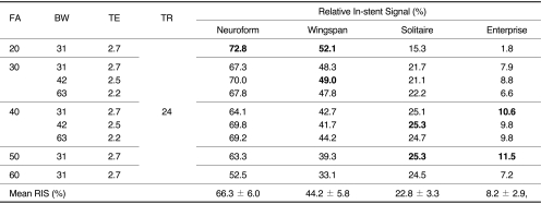
All MR images were obtained on a GE 3.0T scanner (Signa HDx; GE Healthcare, Milwaukee, WI, U.S.A.) with an 8 channel head-coil. At first, we obtained three-dimensional (3D) TOF-MRA with parameters as follows: Spoiled gradient-echo sequence with TR/TE/FA, 24 msec/2.7 msec/20°; FOV/Matrix, 180 mm/384 × 224; slice thickness/slice overlap, 1.2 mm/50%; ASSET factor, 2; and actual bandwidth, 31 KHz. Vein saturation slab or optimized RAMP pulse was not used. We hypothesized that the major artifacts caused by metallic stent were susceptibility artifact and RF shielding artifact, thus we changed FA and BW to minimize these artifacts. The shortest TE was used to minimize signal loss due to dephasing or susceptibility artifact. The shortest TE was ranged from 2.2 msec to 2.7 msec and automatically selected according to the change of BW. The change of FA, BW and TE was shown in Table 1.
A total of 120 slices was sampled in one slab. The scan range was 72 mm. Our imaging parameters yielded a measured voxel size of 0.352 × 0.352 × 0.6 mm. Acquisition time was 2 minutes, 57 seconds.
Image Reconstruction and Interpretation
Source data of each imaging set were reconstructed with the maximal intensity projection (MIP) technique. All the image interpretation of MRA was performed on a PACS monitor by one board-certified radiologist. In-stent signal reduction was assessed by calculating the relative in-stent signal (RIS) inside the stent as compared with background and signal intensity of the tube outside the stent. This was obtained by measuring mean values of signal intensity (SI) from rectangular (at least 5 mm2) regions of interest placed in the lumen of stented segment of the tube, proximal segment of the tube without stent and background filled with ultrasound gel. The RIS was calculated as followed:
RIS (%) = [(SIin-stent - SIbackground) / (SItube - SIbackground)] × 100
The mean and standard deviation for each stent according to various MR parameters were obtained and one-sample t-test were used to select significantly high RIS value of the each stent. The level of statistical significance was set at 0.05. Among the MIP images with significantly high RIS value in each stent, one neuroradiologist, who has been working in MRA interpretation for 9 years, choose one image set with best image quality.
RESULTS
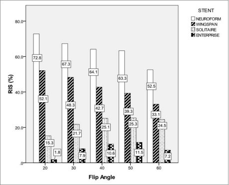
The RIS of each stent according to changes of FA and BW was shown in Table 1. The RIS differed between stent and sequence, and in-stent stent signal reduction occurred in all stents. The mean RIS for Neuroform, Wingspan, Solitaire and Enterprise stent was 66.3 ± 6.0, 44.2 ± 5.8, 22.8 ± 3.3 and 8.2 ± 2.9, respectively. The RIS of Neuroform and Wingspan decreased as the FA increased. However, the RIS of Solitaire and Enterprise increased as the FA increased to the FA value of 50 (Figs. 1, 2). The mean RIS of the all stents according to the change of FA and BW was not significantly different. The significantly high RIS of each stent Neuroform, Wingspan, Solitaire and Enterprise was obtained with FA/BW value of 20°/31 KHz (Neuroform, RIS = 72.8, p = 0.000), 20°/31 KHz and 30°/42 KHz (Wingspan, RIS = 52.1 and 49.0, p = 0.004 and 0.04), 40°/42 KHz and 50°/31 KHz (Solitaire, RIS = 25.3 and 25.3, p = 0.05)and 40°/31 KHz and 50°/31 KHz (Enterprise, RIS = 10.6 and 11.5, p = 0.038 and 0.009), respectively (Table 1, Fig. 3). Among these MIP images with significantly high RIS, images with FA/BW value of 20°/31 KHz (Neuroform and Wingspan), 50°/31 KHz (Solitaire) and 50°/31 KHz (Enterprise) were chosen to be the best (Fig. 3). A band-like artifact was observed at the end of the each stent and a complete signal loss was observed neat the proximal marker of the Solitaire stent (Fig. 3).
DISCUSSION
TOF-MRA can demonstrate pathology of the intracranial large arteries that is less than 3 mm in diameter. However, it is difficult to interpret patency and/or degree of stenosis of stented artery on TOF-MRA because of susceptibility artifact or RF shielding effect of intracranial stents [17,, 19,, 20]. In our daily practice, we observed that the degree of image degradation by these artifacts were variable according to the type of intracranial stents. Thus, we needed to optimize MR parameters according to each intracranial stent.
When we obtain the MRA of intracranial large arteries using TOF, the selection of FA and repetition time is a compromise between saturating background tissue and not saturating blood. Typical FA values range between 20° and 35° for 3D TOF, and these values were applicable to obtaining intracranial large arteries without stent insertion. However, the intracranial stents causes two major types of artifact known as susceptibility artifacts and RF shielding artifacts [18,, 19,, 21,-24]. Thus, to obtain MRA without severe artifacts, we should not consider only factors for increasing contrast between blood and background, but also factors for reducing stent-related artifact.
The RF shielding artifact is caused by eddy currents induced in the electrically conducting wire mesh of the stent [19,, 21,, 22]. These eddy currents produce an opposing RF field, which reduces the sensitivity of receiving and emitting signal within the stent. The RF shielding artifact may be attenuated by increasing RF power of the excitation pulse [21,, 22]. Because the FA is proportional to the integral of the RF pulse, high power RF pulse was required to create an excitation pulse with higher FA. The higher FA is used, the more transverse magnetization is created. Thus, the transverse magnetization of unsaturated blood of fast arterial flow in the imaging plane increases. Although high FA in TOF-MRA may cause signal loss of the peripheral small arteries or arteries with the slow flow due to saturation effect, the proximal portion of intracranial large arteries such as M1 segment of middle cerebral artery or distal internal carotid artery might not be affected saturation effect of high FA. Interestingly, the RIS of Neuroform and Wingspan decreased as the FA increased. However, the RIS of Solitaire and Enterprise increased as the FA increased to the FA value of 50°. Thus, the highest RIS of Neuroform and Wingspan was obtained with FA of 20°, and that of Solitaire and Enterprise was obtained with FA of 40° or 50°. Because the RIS in our experiment was a function of background signal, signal of stented artery and non-stented artery, we could not accurately explain why the trend of the RIS changes according to variable FA value was different in closed- and open-cell design stents. We speculated the effect of reducing RF shielding artifact by using high FA might overwhelm other causes of signal loss of the stented segment.
The stents used in this experiment were made of nitinol, which was known to nonferromagnetic metals and cause negligible signal loss on TOF where the echo time is very short. The thickness of strut and cell design in intracranial stents seemed to be important to determine the degree of RF shielding artifact. The thickness of the strut in the open-cell design stent, Neuroform and Wingspan was 0.07 mm, and that in closed-cell design stents, Enterprise and Solitaire were 0.08 mm and 0.06 mm, respectively [2,-4,, 6,, 25,, 26]. The open-cell design and thinner stent strut of the Neuroform and Wingspan stent might cause lesser RF shielding artifact and provide better image quality as compared with Enterprise stent. Although Solitaire stent has the thinnest stent strut and open slit design, the RF shielding artifact occurred comparable to Enterprise stent due to its closed-cell design. As compared with proximal and distal markers of other stents, the relative thick, proximal marker near the detach zone of the Solitaire stent caused complete signal loss of the lumen due to susceptibility artifact. Thus, it was impossible to evaluate the segment near the proximal marker of the Solitaire stent.
It is known that wider BW can reduce susceptibility artifact and overcome RF shielding effect. However, this might reduce signal to noise ratio of the TOF-MRA [21]. We had expected that wider BW could have reduced RF shielding artifact in closed-cell design stent, and decrease susceptibility artifact. However, the change of the BW did not significantly affect RIS in each stent in our experiment. To overcome RF shielding artifact in closed-cell design stent, it is helpful to use higher flip angle instead of wider BW. The importance of higher FA to overcome RF shielding artifact and narrower BW to improve signal to noise ratio in closed-cell design stent should be emphasized in obtaining MRA using 3D TOF technique.
Our experiment conducted with a silicone tube with straight course. This straight course of our tube resulted in different flow pattern from the in vivo situation, thus artifact and signal reduction may be different in tortuous intracranial large arteries. Moreover, the long axis of the stent in the intracranial large arteries was not always parallel to a main magnetic field. Further in vivo study with various stents should be conducted before clinical application.
In conclusion, the degree of artifact was variable according to the design of each intracranial stent. Thus, MR parameter should be adjusted according to various intracranial stents. The luminal visualization of closed-cell design stents such as Solitaire and Enterprise can be improved by higher FA. Further studies with various stents and patients in clinical practice should be conducted in the near future.