Bench-top Comparison of Physical Properties of 4 Commercially-Available Self-Expanding Intracranial Stents
Article information
Abstract
Purpose
To better understand the performance of four commercially available neurovascular stents in intracranial aneurysm embolization, the stents were compared in terms of their basic morphological and mechanical properties.
Materials and Methods
Four different types of stents that are currently being used for cerebral aneurysm embolization were prepared (two stents per type). Two were laser-cut stents (Neuroform and Enterprise) and two were braided from a single nitinol wire (LEO and LVIS stents). All were subjected to quantitative measurements of stent size, pore density, metal coverage, the force needed to load, push, and deploy the stent, radial force on deployment, surface roughness, and corrosion resistance.
Results
Compared to their nominal diameters, all stents had greater diameters after deployment. The length generally decreased after deployment. This was particularly marked in the braided stents. The braided stents also had higher pore densities than the laser-cut stents. Metal coverage was highest in the LEO stent (14%) and lowest in the Enterprise stent (5%). The LIVS stent had the highest microcatheter loading force (81.5 gf). The LEO stent had the highest passage force (55.0 gf) and deployment force (78.9 gf). The LVIS and LEO stents had the highest perpendicular (37.1 gf) and circumferential (178.4 gf) radial forces, respectively. The Enterprise stent had the roughest stent wire, followed by the LVIS, LEO, and Neuroform stents.
Conclusion
The four neurovascular stent types differed in terms of morphological and physical characteristics. An understanding of this diversity may help to decide which stent is most suitable for specific clinical situations.
In the early 2000s, the Neuroform stent (Stryker) was first introduced and successfully applied clinically in the endovascular coiling of wide-necked cerebral aneurysms. Since then, several new types of neurovascular stent systems that serve the same purpose have been placed on the market. Since these stents aim to prevent the packing coil loops from herniating into the parent artery lumen during coiling of the aneurysm, the Neuroform stent and the new stents all have a self-expanding design [1234]. However, some have an open-cell design while others have a closed-cell design. Moreover, the stents differ in terms of their basic structure and the way they are made. These differences suggest that these stents may not act in an identical fashion during endovascular coiling of aneurysms [5]. It is essential to determine the structural and mechanical differences of each stent as this will provide a thorough overview of the technical aspects of using those stents. This in turn will help the users to determine the stents that are most suitable for specific clinical circumstances and how to use these devices properly [6]. The purpose of this bench-top experimental study was to obtain a better understanding of the performance of four commercially available neurovascular stents in intracranial arteries during coil embolization of cerebral aneurysms. To achieve this, the basic morphological and mechanical properties of the stents were determined.
MATERIALS AND METHODS
Stent selection
Four different types of self-expanding stents that are currently on the market for assisting endovascular coil embolization of cerebral aneurysms were selected. These stents were the Neuroform EZ stent (Stryker, Fremont, CA, USA), the Enterprise stent (Codman Neurovascular, Raynham, MA, USA), the LVIS stent (Microvention, Tustin, CA, USA), and the LEO plus stent (Balt, Montmorency, France). For each stent type, two were used in the tests. The tests consisted of non-destructive (e.g., the deployment and size measurement tests) and destructive (i.e., the corrosion resistance test) tests. Given the limited number of sample stents available, the non-destructive tests were conducted before the destructive tests. Except for the corrosion test, all tests described below were performed with both stents of each type. The corrosion test was only performed with one stent of each type.
Stent size
The stents were prepared as shown in Figure 1. After each stent was loaded with its delivery wire, a magnified picture of the stent was taken under a light microscope (TCA-3.0C; Sungchan Science, Gyeonggi-do, Korea). The undeployed stent diameter and length were then measured from the picture by using dedicated measurement software (TS View; Tucsen, Fuzhou, China) that was provided by the microscope company. The stent was then deployed in a transparent straight glass tube whose inner diameter was 0.5 mm smaller than the nominal stent diameter. After deployment, the stent was removed from the tube, a picture was again taken under the light microscope, and the unconstrained deployed stent diameter and length were measured. These latter measurements were taken because the nominal diameters and lengths of some of the stents may differ depending on their state of deployment. The arithmetic means of the constrained and unconstrained diameters and the constrained and unconstrained lengths were calculated.
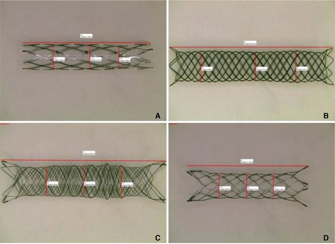
Gross features of the four prepared stent types. (A) The Neuroform stent (4.0 mm diameter, 20.0 mm length). (B) The LEO stent (4.5 mm diameter, 40.0 mm length). (C) The LVIS stent (4.0 mm diameter, 35.0 mm length). (D) The Enterprise stent (4.5 mm diameter, 22.0 mm length).
Pore density and metal coverage
Pore density was calculated by counting the number of pores in a certain area (Fig. 2A). Thus, the stent that had been deployed in the glass tube described above was subjected to gross microscopy (TCA-3.0c; Olympus Corporation, Tokyo, Japan). A picture that was magnified by up to 20-fold was taken and the number of pores was counted as described in Figure 2A. These data were expressed as mean pores/mm2. In addition, the metal coverage, namely, the area of the stent mesh that theoretically contacts the vascular inner surface, was determined (Fig. 2B). This variable was calculated on the basis of the length of the wire (as measured from the microscopic picture) and the thickness of the wire, which was provided by the manufacturer. The mean metal coverage was then calculated for each stent.
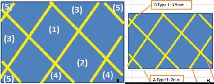
Measurement of pore density and metal coverage.
(A) Pore density was obtained by using the following formulae:
Formula 1:
(1) × 1 + (2) × 0.75 + (3) × 0.5 + (4) × 0.25 + (5) × 0.1 = total number of pores
where (1) = number of whole cells (i.e., cells that were seen in their entirety), (2) = number of slightly cut off cells (i.e., cells that had a small part that could not be seen by the viewer), (3) = number of cells that were cut off by half, (4) = number of cells that had a large part that was cut off, and (5) = number of cells that were almost entirely cut off.
Formula 2: total number of pores/(width × height of viewed area) = pore density
Pore density was expressed as pores/mm2.
(B) Metal coverage was obtained by using the following formulae:
Formula 1: wire length × wire thickness = area of the wire
Formula 2: area of the wire/(width × height) × 100 = % metal coverage
Pushability and trackability
A home-made closed-circuit carotico-aorto-iliac silicone-vascular model was constructed on a bench top (Fig. 3A). A 6-Fr guiding catheter was delivered into the model and the tip was placed about 15 cm proximal to the glass tube segment. The closed circuit was then f illed with warm distilled water. The model was induced to pulsate by applying a peristaltic pump (Ecoline VC-280; Ismatec, Wertheim-Mondfeld, Germany). A microcatheter (XT-27; Stryker Neurovascular, Fremont, CA, USA) was inserted through the guiding catheter. Thereafter, the stent was delivered through the microcatheter by using a universal testing machine (WL2100; Withlab, Gunpo, Gyeonggi-do, Korea) (Fig. 3B). The following variables were measured: (1) the force needed to load the stent into the hub of the delivery microcatheter (loading force), (2) the force required to induce the stent to travel all the way up to the tip of the microcatheter (passage force), and (3) the force required to deploy the stent in the glass tube (deployment force). The arithmetic mean of each force was then calculated.

Measurement of loading, passage, and deployment force. (A) A homemade carotico-aorto-iliac silicone vascular model was used to obtain these variables. A 6-Fr guiding catheter (arrow) and microcatheter (arrow head) were placed inside this system. (B) The stent was loaded in the microcatheter, delivered to the glass tube, and then deployed. The universal testing machine (WL2100; Withlab, Gunpo, Gyeonggi-do, Korea) was used to measure the loading force (i.e., the force needed to load the stent into the hub of the delivery microcatheter), the passage force (i.e., the force required to induce the stent to travel all the way up to the tip of the microcatheter), and the deployment force (i.e., the force required to deploy the stent in the glass tube).
Radial force
Two radial force variables were measured, namely, the perpendicular radial force and the circumferential radial force. The perpendicular radial force is the extrinsic compression force that is needed to induce the stent to recover to its original diameter. It was measured by using the universal testing machine (WL2100; Withlab, Gyeonggi-do, Korea) and applying extrinsic compression parallel to the body of the stent until the diameter of the stent became half of its unconstrained diameter. However, this method is not suitable for all kinds of stents. Therefore, we also measured circumferential radial force by using a different universal testing machine (EM5966; Instron, Norwood, MA, USA) and a radial force tester (RX550; Machine Solutions Inc, Flagstaff, AZ, USA). Thus, the stent was compressed circumferentially under constant velocity until its diameter became half of its unconstrained diameter. The compression force and expansion force needed to induce the diameter of the stent to recover to its original diameter were also measured. The maximum, minimum, and arithmetic mean of each variable were determined.
Surface roughness
To quantify the roughness of the metal surface of the stent mesh, a scanning electron microscope (SEM) (Sirion 400; FEI, the Netherlands) picture of the stent surface that was magnified by up to 5,000 times was taken. Moreover, the chemical composition of the stent was measured by using Energy dispersive X-ray spectroscopy (Super DRYII; Thermo Noran, USA). The roughness of the stent wire was measured quantitatively by using an atomic layer microscope (XE-100; Park Systems Inc., CA, USA).
Corrosion resistance
To evaluate the corrosion resistance of the stent, a 3-electrode system and a potentiostat (VersaSTAT 3; AMETEK, Berwyn, PA, USA) were used. Thus, a flask filled with phosphate-buffered saline (PBS) was placed in a water bath. The temperature of the water was maintained at 37℃. The 3-electrode system, which consisted of one positive electrode and two negative electrodes, was connected to the potentiostat. The stent was placed in PBS and connected to the reference electrode. After purging the PBS with nitrogen gas, the change in electric potential was measured continuously as the currents flowed through the stent. Since corrosion of the stent causes its resistance to drop drastically, the potential value measured at that moment indicates maximal potential.
RESULTS
All of the measurements of the four stent pairs are summarized in Table 1.

Physical Properties of Four Types of Self-Expanding Intracranial Stents
Stent size
In all stents, the loading size was similar to the size indicated by the manufacturer. The unconstrained diameter of the stents, namely, the diameter after deployment in a glass tube, was generally slightly larger than the nominal diameters, especially in the LEO and LVIS stents. The stent length changed in various ways after deployment: the deployed Neuroform stent was slightly longer than its nominal length, the Enterprise length did not change markedly, and the LEO and LVIS stents were substantially shorter after deployment.
Pore density and metal coverage
The LEO and LVIS stents had higher pore densities (0.979 and 0.782 pores/mm2) than the Neuroform and Enterprise stents (both 0.276 pores/mm2). The average metal coverage of the two stents of each stent type varied: the Enterprise stents had the lowest average metal coverage (5.0%), followed by the Neuroform stents (10.0%), the LVIS stents (11.5%), and the LEO stents (14.0%).
Pushability and trackability
None of the stents exhibited deployment failure during the experiments. The LVIS stent had the highest mean loading force (i.e., the force needed to load the stent into the hub of the microcatheter) (81.5 gf), followed by the LEO stent (61.9 gf), the Neuroform stent (19.0 gf), and the Enterprise stent (14.7 gf) (Fig. 4). The LEO stent had the highest mean passage force (i.e., the forced needed to deliver the stent through the microcatheter) (55.0 gf), followed by the Enterprise stent (19.4 gf), the LVIS stent (13.5 gf), and the Neuroform stent (10.5 gf). The LEO stent required the strongest deployment force (i.e., the force needed to deploy the stent) (78.9 gf), followed by the Neuroform stent (53.0 gf), the LVIS stent (42.2 gf), and the Enterprise stent (29.4 gf).
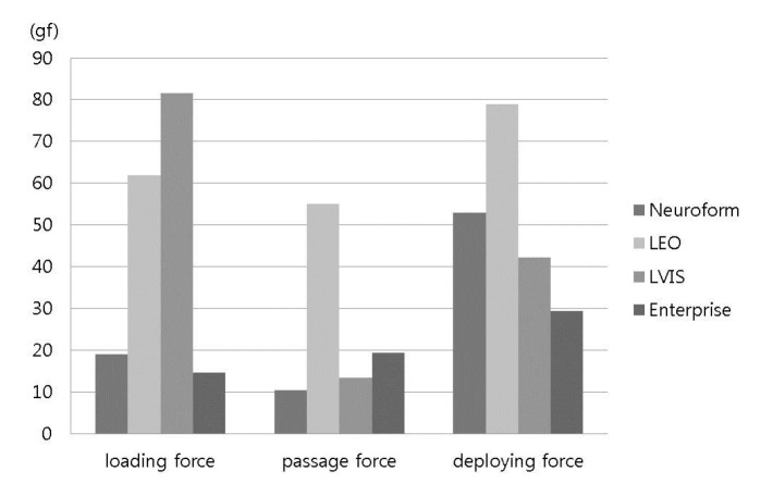
The force needed to deliver and deploy each stent.
Radial force
Radial force was measured in two ways and the two methods exhibited quite disparate trends. The LVIS stent had the highest perpendicular radial force (37.1 gf), followed by the LEO stent (34.2 gf), the Enterprise stent (15.2 gf), and the Neuroform stent (11.4 gf). By contrast, the LEO stents had the highest circumferential radial force (178.4 gf), followed by the Neuroform stent (129.8 gf), the Enterprise stent (120.7 gf), and the LVIS stent (60.4 gf).
Surface evenness
The Enterprise stent had the roughest stent wire (20.3 mm), followed by the LVIS stent (13.7 mm), the LEO stent (10.7 mm), and the Neuroform stent (3.3 mm) (Fig. 5).
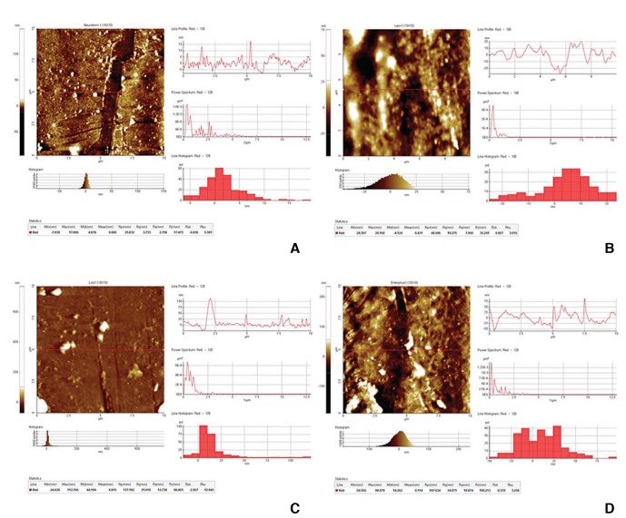
Scanning electron microscope images of the metal surface of the mesh of the stents. (A) The Neuroform stent. (B) The LEO stent. (C) The LVIS stent. (D) The Enterprise stent.
Corrosion resistance
In general, it is considered that a stent is susceptible to corrosion in vivo if the corrosion resistance exceeds 600 mV. Our experiment showed that the Neuroform, LVIS, and Enterprise stents (1040–>1400 mV), but not the LEO stent (570 mV), are susceptible to corrosion.
DISCUSSION
The non-destructive and destructive tests of four commercially available intracranial stents showed that the stents differed in terms of physical properties. These findings may help to indicate which stent is most suitable for particular clinical settings during the endovascular treatment of intracranial aneurysms, as follows.
Before discussing our results, it is necessary to summarize the basic characteristics of the stents that were examined. The Neuroform stent is one of the most widely used stents at present. It is characterized by a tubular mesh that is constructed from zig-zag struts of nitinol and has an open-cell design. Depending on the stent length, the stent consists of four, six, or eight distinct sections. These separate sections are joined by two interconnecting struts. There are eight radiopaque marker bands, four per end, which are secured to tabs on the stent. The stent is available in five diameters (ranging from 2.5 to 4.5 mm) and three lengths (10 mm, 15 mm, and 20 mm). The Enterprise stent has a tubular mesh structure that is generated from nitinol by laser cutting. The ends of the stent are flared and feature four radiopaque tantalum markers at each end. The stent-marker assembly is covered with an insulating polymer. In its expanded shape, the stent creates a highly flexible closed-cell structure [23 7]. The stent is available in one diameter (4.5 mm) and four lengths (14 mm, 22 mm, 28 mm, and 37 mm). The LVIS device consists of a self-expanding closed-cell implant that is generated by braiding of a single nitinol wire. It is a tubular woven mesh closed-cell structure with flared ends. Radiopacity is reinforced with a set of radiopaque wires (tantalum) that are woven into the mesh in a helical configuration. There are also four radiopaque markers at each end. The expanded diameter of the stent can be 3.5 mm, 4.5 mm, or 5.5 mm, while the expanded lengths range from 15 mm to 32 mm. The LEO stent is also a self-expandable intracranial stent. Its closed cell design allows for resheathing and repositioning at up to 90% of deployment. It has two radiopaque wires that extend along its length and allow clear visualization of its diameter and length as well as the parent vessel. Like the LVIS stent, it is generated by braiding from a single nitinol wire and has closed cells that can change in size. It also has greater metal surface coverage than other stents, which can create a flow-diverting hemodynamic effect [2].
Differences between braided and laser cut stents
The present study showed that the laser cut (Neuroform and Enterprise) and braided (LEO and LVIS) stents differed in terms of several properties. In particular, deployment considerably shortened the length of the braided stents. By contrast, the lengths of the laser cut stents did not change substantially after deployment. Such shortening of the braided stents is likely to occur during intracranial aneurysm embolization. Thus, when braided devices are to be placed in small caliber parent arteries, it is necessary to be aware that on deployment the stent will become considerably shorter compared to its length before deployment.
We also observed that the pore density varied markedly between the different stents: the braided stents had considerably greater pore density (0.979 and 0.782 pores/mm2) than the laser cut stents (both 0.276 pores/mm2). This variation is remarkable given the fact that all of these stents have the same purpose. We also found that the braided stents had greater metal coverage (11.5-14%) than the laser cut stents (5-10%). These differences may have clinical implications. First, the mesh of the laser cut stents may be too loose to provide suff icient support when a small-diameter coil is delivered. Second, although the metal coverage of the braided stents did not exceed 16%, their relatively greater pore density and metal coverage may lead to a higher flow diversion effect. In addition, since the arrangement of the filaments of the braided stent can change to adapt to the changing curvature of the parent vessel, the metal coverage of these stents can be heterogeneous. This heterogeneity and the higher flow diversion effect of the braided stents may increase the frequency of occlusion of the branch vessel that originates from the aneurysm neck.
Differences between stents in terms of radial force
Radial force is the force that the stent extends against the vessel wall and the coil mass that is placed inside the aneurysmal sac. Since radial force indicates the capacity of the stent to support the coils inside the aneurysm, it is an important stent variable [8]. When we measured the perpendicular radial force of the stents, we found that they varied from 11.4 and 15.2 gf for the laser cut stents to 34.2 and 37.1 gf for the braided stents. Moreover, previous studies on the same stents report quite different radial forces. These differences may be due in part to the fact that radial force depends on the size of the stent, especially its length [9]. For example, our measurement showed that radial force of 35 mm-long LVIS stent was 25.8 gf, whereas 49 mm-long LVIS stent had a radial force of 48.3 gf. These observations suggest that radial force is only meaningful when the length of the stent is specified.
Another possible reason for the discrepancy between our study and those of others in terms of radial force may relate to the fact that there are two different methods of measuring radial force. These methods differ in terms of whether the extrinsic force that is applied is perpendicular or circumferential [8 10]. We also measured circumferential radial force in our study and found that these results were quite different from perpendicular radial forces of the stents: whereas both braided stents had markedly higher perpendicular radial forces than the laser cut stents, the two laser cut stents and the LEO braided stent had much high circumferential radial forces (129.8, 120.7, and 178.4 gf, respectively) than the braided LVIS stent (60.4 gf).
These observations together mean that the standard radial force specification of stents that is provided by the manufacturer can change depending on stent dimension and the method used to measure radial force. Thus, when considering radial force data, it is necessary to know which measuring method was used and that the radial force of the same stent from the same company can vary depending on its diameter and length.
Stent size affects other physical properties as well
We found that stent size was also a considerable cause of variability in other physical properties. We assessed two differently sized LEO stents: one was 4.5 mm in diameter and 40.0 mm in length, while the other was 3.5 mm in diameter and 18.0 mm in length. We found that despite the fact that they were the same type of stent from the same company, they differed markedly in terms of pore density (0.744 and 1.213 pores/mm2), metal coverage (12% and 16%), loading force (65.1 and 58.6 gf), delivery force (76.4 and 33.6 gf), and deployment force (103.3 and 54.5 gf). Similarly marked disparities in these properties were also observed for the two differently sized LVIS stents.
Other properties
For all of the stents that we tested, the surface roughness and corrosiveness were within the acceptable ranges and the devices did not differ markedly in terms of these variables. This is important information as it helps to simplify the choice when selecting a device for a specific situation.
Limitations of the study
This study has some limitations. First, due to limitations in terms of stent availability, we only tested two individual stents of each stent type. Moreover, in the case of the LEO and LVIS devices, the duplicates differed in length. This limitation means that it was not possible (or it was difficult) to accurately determine the precision of our experiments. Second, the fact that the test stents had already been deployed and manipulated in other tests before we performed the surface roughness and corrosion tests may have influenced the results of the latter tests. Third, and most significantly, we did not compare all intracranial stents that are currently available, including the stents that only recently became available. These include the LVIS blue (Microvention, Tustin, CA, USA), Enterprise 2 (Codman Neurovascular, Raynham, MA, USA), and Neuroform Atlas (Stryker, Fremont, CA, USA) stents. Fourth, our data were obtained by straightforward bench-top experiments. Thus, our results may not be generalizable to real clinical settings.
CONCLUSION
When selecting a stent for intracranial aneurysm embolization, it is necessary to consider the characteristics of the aneurysm, the anatomy of the parent artery, and the purpose of the treatment. A comprehensive understanding of the physical properties of the various stents that are available may aid this decision-making process. Further studies with greater sample sizes and a broader range of stent types are needed to verify our study results.
Acknowledgments
This research was supported by a grant (HO13C0006) from Osong Innovation Center that was funded by the Ministry of Health & Welfare of the Republic of Korea.
Notes
Declaration of conflicts of interest: We declare that we have no conflicts of interest.
