Computational Fluid Dynamics of Intracranial and Extracranal Arteries using 3-Dimensional Angiography: Technical Considerations with Physician's Point of View
Article information
Abstract
We investigate the potentials and limitations of computational fluid dynamics (CFD) analysis of patient specific models from 3D angiographies. There are many technical problems in acquisition of proper vascular models, in pre-processing for making 2D surface and 3D volume meshes and also in post-processing steps for display the CFD analysis. We hope that our study could serves as a technical reference to validating other tools and CFD results.
Computational fluid dynamics (CFD) is an important f ield in mechanical engineering, and also gives physicians interests especially for vascular practices recently. Since the 1950s, CFD is widely utilized in various fields not only in mechanical engineering but also in aeromechanics, marine engineering, civil engineering, meteorological dynamics, environmental engineering, nucleonic and medical engineering. Navier-Stokes' (NS) equation is usually used for analysis of viscous and compressible fluid such as blood [1]. With the advance of computational science, a non-linear NS equation is easy put into practice in CFD analysis instead of the linear NS equation, which converts the variable boundary conditions as simple constants. In contrast with the CFD assumption that the vessel wall is rigid and immovable, fluid structure interaction (FSI), which is integration of CFD with elastic walls such as human bodies, is also of interest in forensic medicine and medical engineering as well as clinical situations [2].
Especially, fluid dynamics of blood flow is relatively familiar to physicians and vascular surgeons, because it is usually used in studies about atherosclerosis or cerebral aneurysm.
Recently CFD studies were published not only biomedical fields of which engineers are the largest part in it, but also clinical fields where physicians play major roles. In many bio-medical journals, researchers have published papers about fluid dynamics largely focused on atherosclerosis and intracranial aneurysms. These studies were well qualified technically, but they were not useful clinically because the studies were performed only in laboratories with time consuming, in vitro models, special equipment and a lot of money [3]. On the other hand, attractive study results were reported on medical articles, but methodological validations and discussions were usually omitted or inadequately described. Because many clinical studies about CFD usually used in-house-developed software [4], most others researchers are faced with difficulties in similar reproducible results. Only a few clinical studies have been reported about CFD except some medical engineering papers in Korea. We aimed to determine the potentials and limitation of CFD analysis in actual clinical fields by using commercial programs with angiography equipment, which can provide three dimensional (3D) imaging format to analyze the CFD.
MATERIALS AND METHODS
Patient specific disease models were retrospectively collected. We enrolled four dimensional vascular models for analysis including a patient with carotid stenosis and three patients with intracranial aneurysm. Data acquisition and reconstruction of 3D vessel geometry from the 3D angiography, which obtained using an AXIOM Artis Zee (Siemens Medical Solution, Erlangen, Germany) digital biplane angiography. The patients' identifying information was deleted from data analysis. This study was approved by our Institutional Review Board after submission of exemption form for informed consent.
Three steps of image post-processing are needed for CFD analysis (Fig. 1). The first step is segmentation for producing the 3D images, which generates the standard template library (STL) files in order to 2nd step processing. The source images could be obtained from CT, MRI or angiography. Conventional 3D angiography is essential for CFD analysis of intracranial arteries because of it's small caliber. Until recently, commercial (such as 3D-Doctor, Lexington, MA, USA) or individual laboratory programs have been used for performing this step in most studies, because it was not possible to generate an STL file with medical 3D software. This work was time-consuming even for experienced engineers with commercial programs that are not specialized for medical modeling. Practical difficulties also existed to engineers because they do not have knowledge of vascular anatomy. In our institution, this f irst step processing is performed using Syngo Workstation (Siemens Medical Solution, Erlangen, Germany) by the physician. The 3D angiographic images were transferred to Syngo workstation to reconstruct the 3D angiography models with large field of view (FOV). After rough editing of unwanted vessels, the region not wanted for CFD analysis, 3D models were saved as a STL file. Most of vascular 3D models, especially for intracranial vessels, Magics ver. 9.5.1 (Materialise, Leuven, Belgium) is used for surface editing. Fine editing of unwanted small perforators or branching vessels was performed. The original STL file is 2D surface triangular mesh that is not suitable for fluid analysis because of its irregular triangular mesh of twisted-section. We re-meshed evenly while preserving the original triangular mesh size of surface of 2D vessel model (Fig. 2). Files were saved as ASCII (American Standard Code for Information Interchange) STL for next step.
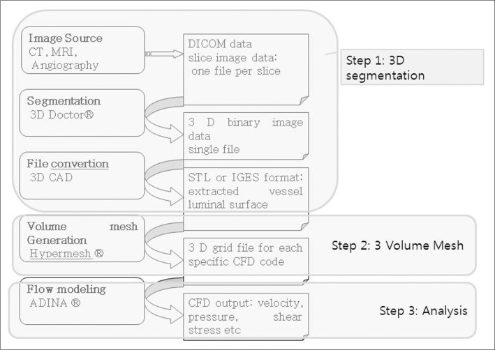
Work flow of Computational fluid analysis.
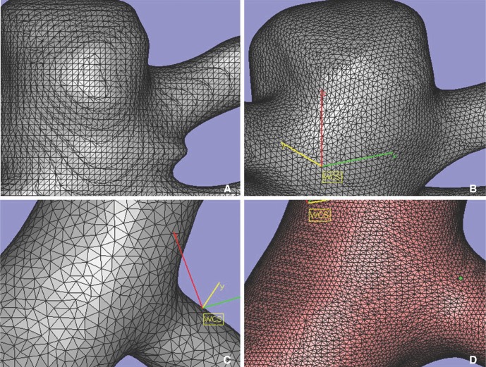
A. Original surface mesh. B. After smoothening. C, D. Various size of triangular mesh by modifying quality threshold and maximum edge length.
The second step is 3D volume meshing with Hypermesh (Altair Engineering, Inc., Auckland, New Zealand). We generated 3D tetrahedral mesh after the correction processing consist of removal of the free edge, elimination of duplicated (overlapping) triangular mesh, removal of the irregular triangular mesh and normalization of inner and outer surface of triangular mesh plane. Files were saved as nastran file for the next step.
The third step is analysis. Computational analysis of blood flow in the blood vessel was performed using the commercial finite element and volume software ADINA version 8.6.2 (ADINA R & D, Inc. Lebanon, MA, USA), using the Navier-Strokes equation.
Blood flow was assumed to be laminar, viscous, Newtonian and incompressible because of its inherent flow characteristics. No-slip boundary conditions were assumed for the flow viscosity produced between the fluid and the wall surface of the blood vessels. Simulations were performed with the following material constants: the blood density was 1,100 kg/m3 and blood dynamic viscosity was 0.004 Poiseuille. To achieve truly patient-specific modeling, the boundary conditions at the inflow boundary were based on the pulsatile periodic flow rate. The unsteady flows in the internal carotid artery were computed over an interval of three cardiac cycles. We only applied atmospheric conditions for outlets. The velocity and flow rate of internal carotid artery was calculated from EKG gated phase contrast angiography (PCA) without any intracranial vascular lesion using Quantitative-flow software Viewforum version R 5.1 (Philips Medical Systems, Best, The Netherlands) (Courtesy of Dae Chul Suh, M.D. Asan Medical Center). We used approximately 100,000 to 300,000 numbers of tetrahedral elements for CFD analysis, and the time step was 30 to 60 times per cardiac cycle for a total of 3 cycles. Finally we assumed final cardiac cycle data as a result [5].
In addition to three major steps of CFD analysis, post-processing steps for visualization of CFD analysis were essential. ADINA module was also used for post-processing of analysis f ile. Blood velocity and eccentricity on vascular cut surface, and wall shear stress in blood vessels were analyzed.
RESULTS
It is essential to generate an STL f ile for CFD analysis. We obtained the source images from conventional angiography with 3D acquisition. Our initial experience of a patient specif ic model with tight stenosis in carotid artery (Fig. 3) was obtained from an angiography workstation (Syngo). The original 3D angiogram of common carotid arteriography was edited using various editing tools (Volume cropping, VOI punching) and saved to STL file using Syngo WS. This editing is essential due to the many branches of external carotid artery, which complicate the next step and contributes to longer analysis process. Artificial features, which occurred from incompletely mixed flow with contrast material and blood in proximal common carotid artery, also must be edited. The first step of CFD analysis was performed minimizing the engineers' help.
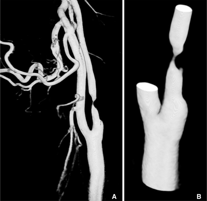
69-year-old male with past history of coronary stenting. A. Original 3D angiogram of common carotid arteriography with tight stenosis in proximal internal carotid artery. B. Edited 3D model before transferring to CFD analysis.
In additional to extracranial 3D models, intracranial 3D models have more irregular surface and it is difficult to make the very small vascular models for the accurate analysis. An important f irst step of CFD analysis is extracting suitable CFD models for hemodynamic analysis. Removing the unwanted small vessels for CFD analysis is necessary (Fig. 4). These works include small and normal branches such as ophthalmic artery, posterior communicating artery and anterior choroidal artery. Small caliber vessels are generally supposed not to significantly affect the CFD analysis. Furthermore, there are several obstacles in vascular models, which making diff icult to CFD analysis. Because of the smaller diameter of intracranial vessels compared to extracranial ones, a high-resolution source image is needed, usually obtained from conventional angiography [4] rather than CT or MRI. However, in conventional angiography, inappropriate position of catheter tip, inadequate rate of contrast medium injection, or type of 3D image acquisition method (Digital subtraction angiography vs. Non-subtracted digital angiography) could result in images not suitable for CFD analysis. If inappropriate source images are obtained in angiography, 3D angiography from subtracted digital radiography can show false lesions in petrous internal carotid artery or middle cerebral artery (Fig. 5). Likewise, if a large aneurysm is located at the tip of basilar artery, distorted donut-shaped 3D models can be obtained by laminar flow effect affected by mixing with blood flow in opposite direction with no contrast agent (Fig. 6). We thought that similar artifact could be also produced in conditions with two inflows such as aneurysm on anterior communicating artery.

35-year-old male presented with subarachnoid hemorrhage. A. Original 3D model, A-com aneurysm noted. B, C. Removing the un-wanted small vessels for CFD analysis using VOI (volume of interest, seeing as yellow lines) punching tools. D. Final vessel model.
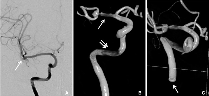
65-old-female presented with subarachnoid hemorrhage. A. Right internal carotid angiogram shows right MCA bifurcation aneurysm (arrow). B. 3D angiography from non-susbtracted distal radiography shows stenotic lesion in MCA (arrow) and petrous carotid artery (double arrow). C. Cutting surface of distal cervical ICA (arrow) show hole like structure due to laminar flow between contrast and contrast non-opacified blood.

41-old-male presented with chief complaint of seizure. A. CT angiogram shows saccular aneurysm in basilar tip. B. Right vertebral arteriography shows laminar flow in basilar artery. C, D. Basilar tip aneurysm shows donut-shaped filling defect due to non-opacified blood.
There were several inappropriate factors for analysis in the surface triangular mesh of generated STL files. Some 3D models show ragged mesh surface around the branch cutting; others show adjacent two vascular lumen appeared to be a bi-lobed single vessel lumen; others show irregular and uneven size and shape of the triangle. Setting the boundary conditions specifying of vascular inlet, outlet and wall is one of the most important steps for CFD analysis. But cut surfaces of the vascular inlet and outlet seem to be ragged margins or not-perpendicular to the vessel wall. This pre-processing step is a very important process in CFD analysis, but time-consuming (Fig. 7). Therefore, preprocessing is recognized as very important step in CFD analysis and more time and effort can be required than for the actual analysis.
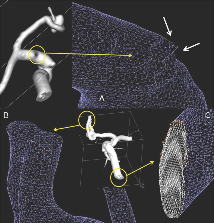
A. Cutting surface of posterior communicating artery show ragged mesh surface. B. Approximated A2 segment of anterior communicating artery looks like bi-lobulated single vessel lumen on surface mesh model. C. Cutting surface of vessel outlet show ragged margin which produce difficulties in boundary definition. There are also showing irregularities of triangle size.
The authors of this study tried to resolve these problems, so the following processes with additional programs were performed additionally. We use Magic's ver. 9.5.1 (Materialize) for editing the vessels walls and rimes, re-meshing, and changing mesh density (Fig. 2). We also use Hyper mesh (Altair Engineering, Inc., Auckland, New Zealand) for removing free edges, eliminating duplicated triangular meshes, and normalization which assign outer and inner wall of vessel. Works with later program took an experienced efforts and times. More than an hour required after the education by engineer. After this process, we generated 3D tetrahedral mesh and stored as nastran file. With our workstation (Windows XP professional x64 edition, Intel® Xeon® CPU, 2.53 GHz, 16GB RAM), final step with ADINA took about 30 minutes to an hour.
Because of the above factors, analysis of intracranial vessels could be possible on the intracranial segment only after removal of the skull base and extracranial segment.
DISCUSSION
Because of increasing interests for CFD analysis in clinical fields, medical venders also interest in their product to add the CFD solvers. We can expect that commercial CFD solvers dedicated to human vascular structures could be released by venders in near future. Many clinicians also hope to use CFD for their daily practice easily. Like other advances in many medical devices and equipments, CFD solvers also require the validation in clinical practices.
This might be the f irst technical review of CFD analysis led by physicians from the viewpoint of clinical practice in Korea. Clinical CFD analysis had been composed actively over the last 10 years, and CFD analysis of intracranial blood vessels has been done in only a few centers. In biomedical engineering or early clinical studies, simplified or unmovable (fixed) models made from computer-aided design were used for fluid analysis [6]. With a simplified model all of the boundary conditions could be applied exactly. However, in the clinical f ields, there are many problems such as unclear boundaries, insuff icient resolution or anatomical problems in analysis of in vivo vascular models. Problems with insufficient resolutions is critically noted in small lesions of intracranial vessels when using low-resolution MR or CT. Exact informative boundary conditions such as flow velocity at outlets are not well recognized. There were no prior in vivo studies that mentioned them, especially outlet conditions.
ADINA analysis took 30 minutes to 1 hour in our study with 3D models of 100,000 ~ 300,000 3D tetrahedral elements. But pre-processing steps using Magic and Hypermesh took much more time and needed mechanical engineer's help. Post-processing with ADINA had also many limitations, because it is not dedicated for post processing tools.
Our some technical challenge of CFD analysis gives us many remained works to do validating our works. These could be validation of optimal 3D mesh options such as number of tetrahedral mesh, adequacy of removing small unwanted arteries, optimal length of vessel distal to region of interest and etc. With the final processing step, adequate def initions of boundary condition are also required. These are input flow condition (laminar vs fully deveopled flow), outlet condition (atmospheric pressure vs flow data), need for patient specific flow data and Etc. There are also task to do after the CFD analysis for so called colorful flow display, CFD. Another dedicated post-processing tool could be helpful. All of above works should be settled near future by many clinical works and model dedicated solutions with single package.
Despite many limitations and technical problems, CFD analysis in the clinical areas of head and neck vascular systems is useful for clinical assessment of risk factors of atherosclerosis of carotid artery [7] or intracranial stenosis [5], risk of aneurismal rupture, and blood flow change before and after partial embolization [8] or flow diverting stents [9].
Low wall shear stress (WSS) is a pathophysiologic factor of atherosclerosis in carotid bulb with respect to hypercholesterolemia [10]. Many reports state that embolic cerebral infarction is associated with rupture of atheromatous plaque and high WSS [11]. These studies have been performed in fixed or static status; however, a recent study by Lee et al. [12] reported that in spite of very little geometrical difference, there was large variation of WSS at carotid bulb. This result may suggest that CFD can be used more actively for longitudinal study of atherosclerosis and for important predictive factors of disease, if more studies and data accumulate.
The limitations of this study are as follows. First, technical and financial problems: Some programs used in CFD analysis for preprocessing were expensive commercial packages. All of these works were needed cooperation with engineers at other institutes or laboratories. In this process, although collaboration between physician and engineers was not easy, many times of meeting and cooperation were necessary. Second, there were some needs for illustrating the CFD results with additional solvers for post-processing; however, we faced on financial problems. Not only a numerical analysis, but also illustrative features such as streamline [9] could be the probe for predictor of aneurysm rupture. We hope the cooperation between industrial-educational institutes could improve the results.
This study is first technical review of CFD in extra and intracranial vessels in Korea. Through this study, we can understand more information and limitations easily overlooked recent published medical journals of CFD analysis about clinical disease models. However, further evaluation will be needed for CFD analysis tools in the clinical settings, and we think this study can provide the basis for clinical and technical considerations.
Notes
This study was partial financially supported by Bracco Imaging Korea.